Introduction
The Great Fen AWS is an experimental AWS installation that we run, located in the Cambridgeshire fens near to our main locations in Ely and Littleport in East Cambs. The station was set up with two main aims:
 To measure weather data in our own locality but at a well-exposed site. Like the great majority of non-Met Office weather observers, the observing sites that we have potentially available at home and office locations are quite significantly compromised in one way or another compared to officially recommended sensor exposures. We were therefore looking for a suitable site in open countryside offering much better sensor exposure and managed to get permission to set up a station at a very open farmland site at a location that we’re referring to as Great Fen, located a few miles roughly to the East of Ely.
- To use the site as a development prototype for a low-cost, remote field AWS with no services to hand but still reporting live weather data to a website. To some extent this was making a virtue of necessity because the site has no mains electricity nor telephone landline either at the site itself or within reasonable wireless relay distance. The only service that is available is mobile phone reception.
Much of the project notes here are therefore to do with the significant problems that this remote field setting presents and the progress that’s been possible in overcoming these hurdles – at least partially – and all within a limited budget. Although we will include some reference to the weather data actually collected, the focus here is on the technical challenges of operating a remote field AWS. Hopefully the experiences reported here will be useful in helping guide other non-professionals seeking to set up an AWS in similar circumstances.
Site description
Basic AWS installation
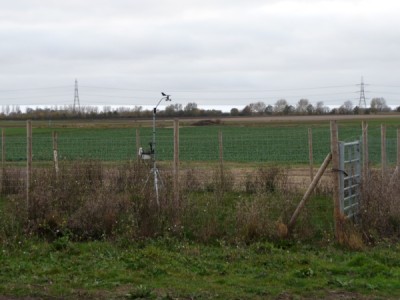
The site lies in open countryside, with the nearest obstruction being a hedgerow about 30m to the East, but other than for this hedgerow (which should have minimal influence in practice, except perhaps modestly in an Easterly wind), the sensors are very well exposed. Although this is a fenland location and therefore essentially at sea-level, the site itself is on a very slight skirt-land rise giving an altitude of perhaps 3-4m amsl and with a sandy clay soil rather than the black fen peat of the main expanse of fields to the West.
The sensor enclosure is a 10m square pen with a wire-mesh fence boundary (see image above – sorry that this isn’t a brilliant photo, will try to replace with a better image at a later date) with excellent – virtually obstruction-free sight-lines for solar and UV sensors, except possibly for immediately around the summer dawn period. Rain gauge is mounted on the ground, T/H sensor at 1.2m and anemometer (currently, but will be raised in the near future) at just 2m.
The weather station instrumentation is a Davis 6152UK wireless Vantage Pro 2 Plus model (ie fitted with solar and UV sensors). The console/receiver and all associated data logging and data link devices are located in a 6×4 wooden shed some 30m away from the enclosure and set into the hedgerow for protection.
Data handling
 The VP2 console/receiver is an Envoy unit (so that the unit will reboot automatically in the event of a power outage), which is fitted with a WeatherlinkIP logger, giving it the capability to stream weather data up to the main Davis www.weatherlink.com website every minute. (Click on the sample image right to see the current live data feed.)
Note: This data feed will not necessarily be live at night-time or in persistent gloomy weather during winter months. The current state of development with the Great Fen AWS site is that the solar power supply is still not yet finally optimised and so there will be periods from November to February when the live data link has shut down to preserve residual battery power for data logging.
We also have a Vantage Vue console fitted with USB logger on site and which is receiving data from the main ISS transmitter in the AWS enclosure: (i) to act as a backup data logging facility; and (ii) to give real-time readings on site for testing/checking purposes.
The WeatherlinkIP logger accesses the Internet via a professional-quality cellular (mobile phone) MultiTech GPRS router/modem. It takes a significant amount of electrical power to run this modem continuously so as to provide a genuinely live (every minute) feed of weather data. Trying to provide adequate winter-time power for this cellular modem while keeping within a budget limit is very much of the focus of this entire Great Fen project and will make up much of the content of the development notes posted in this report.
Solar power supply
 The solar power supply unit (PSU) is the key component of interest in this particular project. All of the AWS instrumentation, the data logging and the GPRS data link used at the Great Fen site are relatively standard implementations and therefore not really needing detailed comment here. But without the solar PSU at this remote field site, a live data feed would be impossible. So the story of the evolution and performance of the solar PSU will take centre stage in this project.
A more detailed discussion of whys and wherefores behind the detailed specification of the solar PSU and future ideas/testing for further evolution will be found on the separate development notes page. Here we’re just providing an outline of the current (Nov 2011) specification which, as with any solar PSU, comprises three main components:
- Solar panel – two separate 12v 30W panels in this case;
- A deep cycle 12v battery, initially specified at 65Ah capacity;
- Charge regulation, voltage supplies and monitoring circuitry;
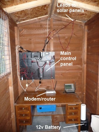
The control circuitry – all housed on a control panel pictured right – is the only item needing further comment here. The solar panels and battery are both specified as standard 12v parts and this voltage is also fine for powering the cellular modem/router. However, all VP2 consoles are powered as standard by a 5v supply and the maximum supply voltage allowed is 6v. So a separate regulated supply is needed for the console, leading to a requirement for both 5v and 12v supplies from the solar PSU to the data devices.
Because this is an experimental prototype, installed at a remote field site where access isn’t always easy in winter, we have wanted to monitor and log the performance of the various components (battery and supply voltages etc) as much as possible. This has resulted in the wiring for the control panel appearing to be much more complex than it would otherwise need to be. So don’t be deceived by this picture – a standard solar PSU would look much simpler than this experimental set-up, though of course some minimal amount of wiring would still be necessary.
Much more detail on the design and performance of the solar PSU, including close-ups of the control panel, will be found on the solar PSU page.